Mr. Lukka takes a look at VRML basics including scripting, animation and applications.
VRML is intended to be for virtual reality what HTML is for text—a structured, standard, cross-platform format for static or interactive hyperlinked content. Just like HTML, it can be written by hand or generated by a program (the latter is usually preferable).
About a year ago VRML was catching on quickly, but much of that enthusiasm seems to have faded. It has not yet taken its place alongside HTML, JPEG and CGI as one of the basic, widely deployed web technologies.
One reason why this might be true is that no workable VRML browser for Linux or other UNIX-like operating systems is available. The ones that do exist are incomplete and generally not able to display web content in VRML well enough for serious use. For example, the cross-platform offerings are not able to handle Script nodes, which are one of the most important additions to the new VRML97.
My theory as to why this might influence the general acceptance of VRML is that a large fraction of people who are interested in cool technologies are using Linux and do not want to support an application that does not work with Linux and other properly working operating systems.
My scientific work needs the interactive visualization that VRML provides. While many different 3-D packages are available, VRML has the advantage in that it supports many sorts of interactions with the scene. Also, I would be able to send the diagrams I made with it to colleagues by e-mail.
After finding the available browsers to be unsatisfactory, I decided to write my own VRML browser. This browser, called FreeWRL, is rapidly approaching VRML97 specification compliance, and supports most of the capabilities lacking in other Linux browsers. I wrote it in Perl, as it was the only language that would enable me to get it working quickly.
With the availability of FreeWRL, I think many free OS users might wish to evaluate or re-evaluate VRML. In this article, I’ll attempt to lay out the basic concepts of VRML and explain how it might be useful.
To run the code listed here, you need a VRML browser. If you don’t have one, and are running Linux or some other UNIX-like OS, go to http://www.iki.edu/lukka/freewrl/ and follow the installation instructions.
Notice in particular the words “if you have any trouble, e-mail me.” The very worst thing you can do with free software is to download it, see that it doesn’t work for some reason, leave it, and tell your friends that it doesn’t work. The author will never know what is wrong with his package and will not be able to improve it, while rumors will be spreading everywhere that the package is not worth trying. Good bug reports are the least you can do for free software developers in return for their effort. “Thank-you” e-mail is nice, but not nearly as vital.
The Basics
Instead of a lengthy description, let’s start with the code for drawing a simple world (see Listing 1). We’ll start with the inner section: a sphere is described with a radius of 0.5. (In VRML, the units are usually called meters but that is just a convention.) This sphere is the geometry of a Shape node, whose “appearance” has a diffuseColor of 0.8 0 0, i.e., very bright red. Therefore, the Shape actually describes a red sphere. This shape is one of the children of a Transform, whose translation is 0 1 0, i.e., one meter upwards on the Y axis, which, from the default viewpoint on the positive Z axis, is up. The first line is a comment telling the browser this file is written in VRML version 2.0.
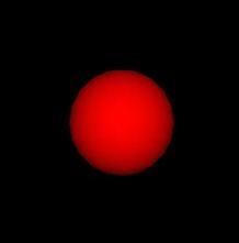
Figure 1
In short, we have just described a red sphere with a radius of half a meter and lying one meter above the origin. (See Figure 1.) Now the code in Listing 1 may seem a somewhat onerous way of describing such a simple scene. For example, the following might be easier:
Listing 1.
#VRML V2.0 utf8
   Transform {
   translation 0 1 0
   children [
       Shape {
         appearance Appearance {
            material Material {
                diffuseColor 0.8 0 0
            }
         }
         geometry Sphere {
            radius 0.5
         }
      }
   ]
}
# THIS IS NOT LEGAL VRML—SEE TEXT
Sphere {
        center 0 1 0
        radius 0.5
        color 0.8 0 0
}
In fact, you can do this: it is possible to create your own nodes suitable for your own application using prototypes, which are similar in spirit to preprocessor macros in C, as shown in Listing 2.
Listing 2
#VRML V2.0 utf8
# Define a PROTOtype:
# A Thing with a given center and color
PROTO Thing [
   field SFVec3f center 0 0 0
   field SFColor color 0.8 0 0
   field SFNode thing NULL
] {
   Transform {
      translation IS center
      children [
         Shape {
            appearance Appearance {
               material Material {
                  diffuseColor IS color
               }
            }
            geometry IS thing
         }
      ]
   }
}

# Use the PROTOtype for displaying various things
Thing {   # Small red box at origin
   thing Box { size 0.5 0.5 0.5 }
}
Thing {   # Red sphere at 1.5 meters up from origin
   center 0 1.5 0
   thing Sphere { }
}
Thing {   # Blue cone at 1 meter right from origin
   center 1 0 0
   color 0 0 0.8 g
   thing Cone { }
}
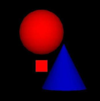
Figure 2
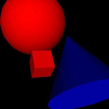
Figure 3
The scene described by the code in Listing 2 is shown from two different angles in Figures 2 and 3. Now you can define any number of scenes like this, using the PROTO you just defined. Of course, you do have to deal with including the original PROTO in the beginning. It is also possible to refer to it in another file using so-called EXTERNPROTOs, which include the interface part (in brackets) but omit the definition (in braces). Even this might sometimes feel like too much typing. In that case, you can easily write a Perl script to include the correct PROTOs in your VRML files, or to do whatever other repetitive tasks you need done.
In scene graphs, you can give a node a name using the DEF statement and use it again in another place with a USE statement—see Listing 3.
Listing 3
#VRML V2.0 utf8
Shape {
   appearance DEF APP Appearance {
      material Material {
         diffuseColor 0.8 0 0
      }
   }
   geometry Box { }
}
Transform {
   translation 0 2 0
   children [
       Shape {
         appearance USE APP
         geometry Sphere {
            radius 0.5
         }
      }
   ]
}
Note that unlike with PROTOs, where a complete copy of the contents of the prototype is made, only one Appearance node is present, which is referred to in two places. For example, if we later animate the appearance to change the color from red to blue, both the box and the sphere change color; whereas if we animate the color of a Thing in the PROTO example, only that one Thing changes color. Once a node has been named with DEF, it can be used in USE statements any number of times.
Now that you have a sense of what is going on, let’s have a more formal description of what we just did. A VRML world is described as a hierarchy of nodes called the scene graph. Each node is of a particular node type, and for each node type the VRML97 specification defines various fields. Each field has a type and a default value. The syntax for a node is
NodeType {
        field value
        field value
        ...
}
where the syntax for a value depends on the type of the field. For example, the value of an SFVec3f is three floating-point numbers and the value of an SFNode is another node just like above.
The single-valued (SF) field types are:
- SFBool: a Boolean value, written TRUE or FALSE
- SFFloat: a floating-point number
- SFImage: an image, described by several integer values, first width, height and number of components, then width*height values for the pixels
- SFInt32: a 32-bit integer
- SFNode: a node
- SFRotation: a rotation: 3 floating-point values for an axis and one for the angle in radians
- SFString: a string in double quotes. Inside, double quotes and backslashes are quoted by a backslash
- SFTime: a floating-point value, time in seconds since a specific origin
- SFVec2f: a two-dimensional vector containing two floating-point values
- SFVec3f: a three-dimensional vector containing three floating-point values
For most SF field types there exists a corresponding MF field type, which simply means zero-or-more values of the corresponding SF type. For example, the following would be legal values for a MFVec3f field:
[]
0.1 2 3
[0.1 4 2]
[0.5 2 6 1 6 4 7 4 6]
[0.5 2 6, 1 6 4, 7 4 6]
That is, the values may or may not be separated by commas and must be surrounded by brackets if there are more or less than one of them.
These names for the field types are also used inside the PROTO declarations: the syntax of a PROTO is basically
PROTO Name [
        field Type fieldName defaultvalue
        exposedField Type fieldName defaultvalue
        eventOut Type fieldName
        eventIn Type fieldName
        ...
] {
        Node { ... }
        ...
}
where inside the PROTO body, field values can also be specified using IS statements, which equate that field with one of the published fields of the PROTO (e.g., the center field of the Thing PROTO above).
For descriptions of all the node types and their fields as well as the exact grammar and semantics of VRML, see the VRML97 specification (found at http://www.vrml.org/) or a book. Figure 3 shows Netscape displaying the definition for the IndexedFaceSet node (which makes it possible to describe arbitrary polygonal geometry) from the web site.
This is basically all you need to know to create static VRML scenes, except for the nitty-gritty details which you can find in the above-mentioned source. Once you do create worlds using FreeWRL, send me a note by e-mail and I’ll put a link to your worlds on the FreeWRL web page.
Animation and Interaction
Of course, creating static scenes is not such a big deal. The truly interesting part of VRML is its ability to interact with the user. Suppose you want to demonstrate the concept of a cross product of two vectors to a friend. You can draw all sorts of 2-D diagrams, but what would be a better description than a 3-D graph in which your friend could adjust two vectors and see the cross product change in real time (especially since you can embed it into a web page using the HTML embed tag)? One of the FreeWRL demos (Figure 4) does exactly this, plus the vector sum and difference.
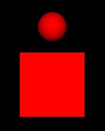
Figure 4
In the previous section, you saw how the Nodes describe the scene to be rendered. What I didn’t mention is that nodes can send events to each other along specified routes. The event routes are independent of the scene hierarchy.
Routes are specified by ROUTE statements. For example, Listing 4 creates a white box (Figure 5), which cycles smoothly through red and blue when clicked, returning to white 2.5 seconds after the click. What happens when you click on the box? First, the BUTTON node senses it (most sensors in VRML sense events from their siblings, in this case the Shape node defining the box) and sends a touchTime event. The ROUTE statement causes that event to be routed into the startTime of the TimeSensor TS, which causes it to start generating time events for one cycle (the length of the cycle is 2.5 seconds). At each clock tick, the TimeSensor sends an event called fraction_changed with an SFFloat value between 0 and 1 (giving the fraction of the time in the cycle that has gone by). This event is then routed to CI which is a ColorInterpolator, i.e., it does piecewise linear interpolations of color values. CI then sends a value_changed event that MAT receives as diffuseColor, then the color of the box changes. For example, if CI receives a set_fraction event with the value 0.3, it checks its key field and notices that 0.3 is between the first and second value. It is six tenths of the way to the second value; therefore, the output is the color (0.6 0.6 0.6).
Listing 4
#VRML V2.0 utf8

DEF TS TimeSensor {
 g cycleInterval 2.5
}

DEF CI ColorInterpolator {
   key [0 0.33 0.67 1]
   keyValue [1 1 1, 1 0 0, 0 0 1, 1 1 1]
}

Group {
 children [
 DEF BUTTON TouchSensor { }
 Shape {
 ggeometry Box { }
 gappearance Appearance { material DEF MAT Material { } }
 }
 ]
}

ROUTE BUTTON.touchTime TO TS.startTime
ROUTE TS.fraction_changed TO CI.set_fraction
ROUTE CI.value_changed TO MAT.diffuseColor
Having events go through an interpolator to reach their destination is a fairly common idiom in VRML, as this allows you to specify arbitrary mappings relatively easily and cheaply. Several different kinds of interpolators are in the VRML97 specification, for different data types.
Scripting
However, interpolators will take you only so far: for one thing, they can’t toggle on a light at a particular point in the sequence. It would have been easy for the VRML97 specification authors to add a node type to accomplish this, but they chose not to. Instead, they chose to create a very general interface to external scripting languages, Java and JavaScript. You can define arbitrary behaviours for your world using these programming languages.
If we want to have the Box in the previous example disappear and be replaced by a small blue sphere for the first 1.5 seconds of each cycle, we need to use a Script node. This particular example is shown in Listing 5. The TS and CI nodes and the routes between them and MAT are the same as in the previous example.
Listing 5
DEF SCR Script {
      eventIn SFFloat set_fraction
      field SFInt32 curchoice 0
      eventOut SFInt32 choice
      url "javascript:
         function set_fraction(val,time) {
            if(val < 0.6 && curchoice == 0) {
               choice = 1;
               curchoice = 1;
         } else if(val >= 0.6 && curchoice == 1) {
               choice = 0;
               curchoice = 0;
            }
         }
      "
   }
 g DEF BUTTON TouchSensor { }
   DEF SW Switch {
    gchoice [
      Shape {
       geometry Box { }
       appearance Appearance { material DEF MAT
          Material { } }
      }
      Shape {
       geometry Sphere { radius 0.5 }
       appearance Appearance { material Material
          { diffuseColor 0 0 0.8 } }
      }
    g]
   }
   ROUTE TS.fraction_changed TO SCR.set_fraction
   ROUTE SCR.choice TO SW.whichChoice
As is obvious from the example, the syntax of specifying fields inside the Script node is similar to the PROTO interface section: instead of just saying fieldName value we are saying kind Type fieldName followed by value for fields. This is because the specification defines only three fields for the Script node: url, directOutput and mustEvaluate and leaves it up to the programmer to define the eventIns, fields and eventOuts of his script.
The actual script inside the Script node is specified in the url field. In this case, it is written in JavaScript and is embedded into the URL. It would also have been possible to write the script into a file (with the .js suffix) and to refer to that file in the URL. Alternatively, the script could have been written in another scripting language (e.g., Java or Perl).
Applications
So far, we’ve discussed how to write VRML. However, the most interesting results come from creating VRML automatically. Static worlds that are programmed once are interesting mostly for games, art or advertisements. Great possibilities remain to be exploited in the interface between the rest of the information world and the 3-D browser.

Figure 5
Also, we can use the API provided by the browser to create an application that uses VRML to provide a part of the GUI. A fairly simple interface can be written as a Perl program that uses the FreeWRL browser and GTK together to provide a user interface, which would be difficult to do in VRML or GTK alone. The main window consists of an entry into which you can enter a function you want the program to plot, a button to plot it, and three labels showing the X,Y coordinates and the function value at the point where your mouse last touched the function surface. The program also places a blue box at this point in the 3-D window. It would be trivial to add code to take 2-D or 3-D snapshots of this scene, as either the usual image files (GIF/JPEG) or VRML, once you have the scene displayed in the browser.
Basically, in addition to creating the GTK GUI, the code simply creates a browser window, loads a VRML world from a string and then calls a browser method to obtain a reference to an ElevationGrid node in the scene. It then sends events to this ElevationGrid to set the shape of the surface via the height field. The program also registers a listener for a TouchSensor node in the scene, so it is able to obtain the mouse position on the surface. The really interesting thing is that all the code for this application is under 200 lines with comments. (The application is included in the FreeWRL distribution, so I will not include the full source code here.)
It is also possible to access the VRML browser through a Java API called EAI (external authoring interface). This enables one to write web applets that access a VRML scene. At the time of this writing, FreeWRL partially implements the Java EAI API but isn’t yet able to provide this API while running inside Netscape. By the time you read this article, this situation may have changed.
Conclusions
Rather than writing a complete tutorial, I’ve tried to give an overview of what VRML is and what it might be useful for. I hope I’ve provided some new ideas that you can put to use at the right time. If you need more complete references, links to many sources can be found at http://www.vrml.org/, the web site of the VRML Consortium. The FreeWRL home page is at http://www.iki.fi/lukka/freewrl/ (iki.fi is a redirector to wherever the home page happens to be at the time).
All listings referred to in this article are available by anonymous download in the file ftp.linuxjournal.com/pub/lj/listings/issue57/3085.tgz.
 Linux, Linux OS, Free Linux Operating System, Linux India Linux, Linux OS,Free Linux Operating System,Linux India supports Linux users in India, Free Software on Linux OS, Linux India helps to growth Linux OS in India


